Purdue Model

Overview
The Purdue model is derived from the Purdue Enterprise Reference Architecture (PERA) model, which is a widely used conceptual model that describes the internal connections and dependencies of important components in ICS networks. The Purdue model is also known as the Industrial Automation and Control System reference model.
The Purdue model consists of three zones: the manufacturing zone (OT) and enterprise zone (IT), separated by a demilitarized zone (DMZ), which is used to restrict direct communication between the OT and IT systems. The intention behind adding this extra layer is to confine the network or system compromises within this layer and provide uninterrupted production. The three zones are further divided into several operational levels.
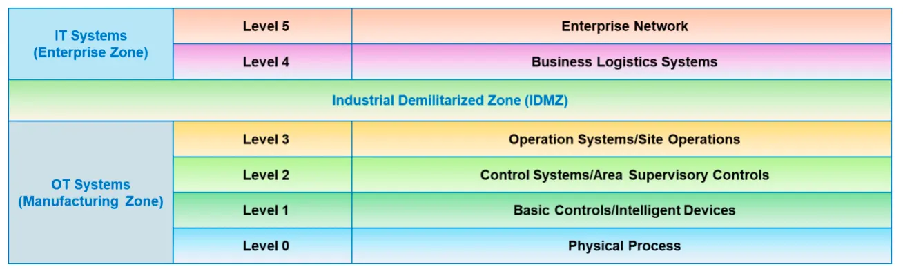
Zones and Levels
Enterprise Zone (IT Systems)
The enterprise security zone is a part of IT, in which supply-chain management and scheduling are performed using business systems such as SAP and ERP. It also locates the data centers, users, and cloud access. The enterprise zone consists of two levels.
Level 5 (Enterprise Network)
This is a corporate level network where business operations such as B2B (business-to-business) and B2C (business-to-customer) services are performed. Internet connectivity and management can be handled at this level. The enterprise network systems also accumulate data from all the subsystems located at the individual plants to report the inventory and overall production status.
Level 4 (Business Logistics Systems)
All the IT systems supporting the production process in the plant lie at this level. Managing schedules, planning, and other logistics of the manufacturing operations are performed here. Level 4 systems include application servers, file servers, database servers, supervising systems, email clients, etc.
Protocols Used in Level 5 and Level 4:
- DCOM: DCOM (Distributed Component Object Model) is Microsoft's proprietary software that enables software components to communicate directly over a network reliably and securely
- FTP/SFTP: FTP establishes a connection to the specific server or computer, and it is also used to download or transfer files. SFTP verifies the identity of the client, and once a secured connection is established information is exchanged
- GE-SRTP: GE-SRTP (Service Request Transport Protocol), developed by GE Intelligent Platforms, is used to transfer data from PLCs, and runs on a selected number of GE PLCs that turn digital commands into physical actions
- IPv4/IPv6: IPv4 is a connectionless protocol used in packet-switched networks. IPv6 is used for packet-switched internetworking, which provides end-to-end datagram transmission across multiple IP networks
- OPC UA: This protocol ensures reliable, secure, and platform-independent exchange of data across different manufacturing devices and between these devices and enterprise systems
- TCP/IP: TCP/IP is a suite of communication protocols used for the interconnection of networking devices over the Internet
- SMTP, HTTP/HTTPS: Standard Internet protocols used for email communication, file transfers, and data transmission across enterprises
- Wi-Fi: Wi-Fi is a technology that is widely used in wireless local area networking or LAN. The most common Wi-Fi standard used in homes or companies is 802.11n, which offers a maximum speed of 600 Mbps and a range of approximately 50 m
IDMZ == Level 3.5
Manufacturing Zone (OT Systems)
All the devices, networks, control, and monitoring systems reside in this zone. The manufacturing zone consists of four levels.
Level 3 (Operational Systems/Site Operations)
In this level, the production management, individual plant monitoring, and control functions are defined. Production workflows and output of the desired product are ensured at this level. Production management includes plant performance management systems, production scheduling, batch management, quality assurance, data historians, manufacturing execution/operation management systems (MES/MOMS), laboratories, and process optimization. Production details from lower levels are collected here and can then be transferred to higher levels or can be instructed by higher-level systems.
Protocols Used in Level 3:
- CC-Link: A CC-Link (Control and Communications Link) is an open industrial network that enables devices from different manufacturers to communicate. It is used in machine, process control, and building automation
- HSCP: Hybrid SCP (Secure Copy Protocol) is developed for transmitting larger file sizes at high speed on long-distance and wideband infrastructure
- ICCP (IEC 60870-6): ICCP (Inter-Control Center Communications Protocol) (IEC 60870-6) provides a set of standards and protocols for covering ICS or SCADA communication in power system automation
- IEC 61850: IEC 61850 is a common protocol that enables Interoperability and Communications between the IEDs at electrical substations
- IEC 60870-5-104: A protocol used for telecontrol in electrical engineering and power system automation, which is common in utilities
- ISA/IEC 62443: ISA/IEC 62443 provides a flexible framework for addressing and mitigating current and future security vulnerabilities in industrial automation and control systems
- Modbus: Modbus is a serial communication protocol that is used with PLCs and enables communication between many devices connected to the same network
- NTP: NTP (Network Time Protocol) is a networking protocol that is used for Clocks synchronization between computer systems over packet-switched and variable-latency data networks
- Profinet: Profinet is a communication protocol used to exchange data between controllers like PLCs and devices like RFID readers
- SuiteLink: SuiteLink protocol is based on TCP/IP and runs as a service on Windows operating systems. It is mostly used in industrial applications that value time, quality, and high throughput
- Tase-2: Tase-2, also referred to as IEC 60870-6, is an open communication protocol that enables the exchange of time-critical information between control systems through WAN and LAN
- ControlNet: A real-time control protocol is used to collect data from and send instructions to the field devices. It provides a high-speed transmission and is particularly robust in noisy environments
- Profibus PA/DP: Used to automate tasks at the plant level. Profibus decentralized peripherals (DP) are used to operate sensors and actuators via a central controller, whereas Profibus process automation (PA) is used to monitor the measuring equipment through a process control system
Level 2 (Control Systems/Area Supervisory Controls)
Supervising, monitoring, and controlling the physical process is carried out at this level. The control systems can be DCSs, SCADA software, Human–Machine Interfaces (HMIs), real-time software, and other supervisory control systems such as engineering works and PLC line control.
Protocols Used in Level 2:
- 6LoWPAN: IPv6 over Low Power Personal Area Networks (6LoWPAN) is an Internet Protocol used for communication between smaller and low-power devices with limited processing capacity; it is mainly used for home and building automation
- DNP3: DNP3 (Distributed Network Protocol 3) is a communication protocol used to interconnect components within process automation systems
- DNS/DNSSEC: Domain Name System Security Extensions (DNSSEC) provide a way to authenticate DNS response data and can secure information provided by DNS
- FTE: Fault Tolerant Ethernet (FTE) is designed to provide rapid network redundancy, and each node is connected twice to a single LAN through dual network interfaces
- HART-IP: The HART-IP protocol is used to integrate WirelessHART gateways and HART multiplexers tightly and efficiently for sending and receiving digital information
- IEC 60870-5-101/104: This is an extension of the IEC 101 protocol with some modifications in transport, network, link, and physical layer services. It enables communication between the control station and substation through the standard TCP/IP network
- SOAP: SOAP (Simple Object Access Protocol) is a messaging protocol containing a stern set of rules that can administrate data transfer between client and server using the XML message format
- DeviceNet: Used to connect simple industrial devices such as sensors and actuators with higher-level devices such as PLCs. It runs on controller area network (CAN) technology
- AS-Interface (AS-i): This is a simple and cost-effective network designed to connect binary devices such as actuators and sensors in automation applications
Level 1 (Basic Controls/Intelligent Devices)
Analysis and alteration of the physical process can be done at this level.
Analysis and alteration of the physical process can be done at this level. The operations in basic control include "start motors," "open valves," "move actuators," etc. Level 1 systems include analyzers, process sensors, and other instrumentation systems such as Intelligent Electronic Devices (IEDs), PLCs, RTUs, Proportional Integral Derivative (PID) controllers, Equipment Under Control (EUC), and Variable Frequency Drives (VFDs). PLCs was used in level 2 with a supervisory functionality, but it is used as a control function in level 1.
Level 0 (Physical Process)
In this level, the actual physical process is defined, and the product is manufactured. Higher levels control and monitor operations at this level; therefore, this layer is also referred to as Equipment Under Control (EUC). Level 0 systems include devices, Sensors (e.g., speed, temperature, pressure), Actuator, or other industrial equipment used to carry out the manufacturing or industrial operations. A minor error in any of the devices at this level can affect overall operations.
Protocols Used in Level 1 and Level 0:
- BACnet: BACnet (Building Automation and Control network) is a data communication protocol designed for building automation and control networks that implements standards such as ASHRAE, ANSI, and ISO 16484-5
- EtherCAT: Ethernet for Control Automation Technology (EtherCAT) is an Ethernet-based fieldbus system that is appropriate for both hard and soft real-time computing necessities in automation technology
- CANopen: CANopen is a high-level communication protocol based on the CAN (Controller Area Network) protocol. It is used for embedded networking applications like vehicle networks
- Crimson: Crimson is the common programming platform used for a variety of Red Lion products such as G3 and G3 Kadet series HMIs, Data Station Plus, Modular Controller, and the Productivity Station
- DeviceNet: DeviceNet is another variant of the Common Industrial Protocol (CIP) that is used in the automation industry for interconnecting control devices to exchange data
- Zigbee: Zigbee is a short-range communication protocol that is based on IEEE 203.15.4 standard. Zigbee is used for devices that transfer data intermittently at a low data rate in a restricted area and within a range of 10–100 m
- ISA SP100: ISA SP100 is a committee for establishing the industrial wireless standard ISA100. ISA100 is used for the industrial manufacturing environment and process automation industry
- MELSEC-Q: MELSEC-Q provides an open and seamless network environment integrating different levels of automation networks such as CC-Link IE, high-speed, and large-capacity ethernet-based integrated open networks
- Niagara Fox: Niagara Fox protocol is a building automation protocol used between the Niagara software systems developed by Tridium
- Omron Fins: Omron Fins is used by PLC programs for transferring data and performing other services with remote PLC connected on an Ethernet network. It can also be used by remote devices such as FieldServer for transferring data
- PCWorx: PCWorx is used in many ICS components, and they make a series of inline controllers (ILCs). These controllers allow the use of different ICS protocols and some common TCP/IP protocols
- Profibus: Profibus is more complex than Modbus, and is designed and developed to address interoperability issues. It is employed in process automation and factory automation fields
- Sercos II: The serial real-time communication system (Sercos II) comprises a digital drive interface appropriate for use in industrial machines. It is used in complex motion control applications with high specification designs
- S7 Communication: S7 Communication is a Siemens proprietary protocol that runs between programmable logic controllers (PLCs) of the Siemens S7-300/400 family and is used in PLC programming and for accessing PLC data from SCADA
- WiMax: Worldwide Interoperability for Microwave Access (WiMax) is based on the standard IEEE 802.16 and is envisioned for wireless metropolitan area networks. WiMax operates at frequencies between 2.5 GHz and 5.8 GHz with a transfer rate of 40 Mbps
- FOUNDATION Fieldbus: This network protocol for building automation provides an all-digital communication infrastructure for control. It is particularly common in process industries, where it links field instruments, such as actuators and sensors, to control systems
Industrial Demilitarized Zone (IDMZ)
The demilitarized zone is a barrier between the manufacturing zone (OT systems) and enterprise zone (IT systems) that enables a secure network connection between the two systems. The zone is created to inspect overall architecture. If any errors or intrusions compromise the working systems, the IDMZ holds the error and allows production to be continued without interruption. IDMZ systems include Microsoft domain controllers, database replication servers, and proxy servers.
graph TB
    subgraph Enterprise["ENTERPRISE ZONE (IT Systems)"]
        L5["Level 5: Enterprise Network
Corporate operations, B2B/B2C services
Internet connectivity, inventory reporting"]
        L4["Level 4: Business Logistics Systems
Application servers, file servers, database servers
Production scheduling and planning"]
    end

    subgraph DMZ["INDUSTRIAL DMZ"]
        IDMZ["Security Barrier
Domain controllers, database replication
Proxy servers"]
    end

    subgraph Manufacturing["MANUFACTURING ZONE (OT Systems)"]
        L3["Level 3: Operational Systems
Production management, MES/MOMS
Data historians, quality assurance"]
        L2["Level 2: Control Systems
SCADA, DCS, HMI
Supervisory control, PLCs"]
        L1["Level 1: Basic Controls
PLCs, RTUs, IEDs
Sensors, actuators, analyzers"]
        L0["Level 0: Physical Process
Manufacturing equipment
Sensors, actuators, industrial devices"]
    end

    L5 --> L4
    L4 --> IDMZ
    IDMZ --> L3
    L3 --> L2
    L2 --> L1
    L1 --> L0

    style Enterprise fill:#e3f2fd,stroke:#1976d2,stroke-width:3px
    style DMZ fill:#fff3e0,stroke:#f57c00,stroke-width:3px
    style Manufacturing fill:#f3e5f5,stroke:#7b1fa2,stroke-width:3px
    style IDMZ fill:#ffe0b2,stroke:#e65100,stroke-width:2px
    style L5 fill:#bbdefb,stroke:#1976d2,stroke-width:2px
    style L4 fill:#bbdefb,stroke:#1976d2,stroke-width:2px
    style L3 fill:#e1bee7,stroke:#7b1fa2,stroke-width:2px
    style L2 fill:#e1bee7,stroke:#7b1fa2,stroke-width:2px
    style L1 fill:#e1bee7,stroke:#7b1fa2,stroke-width:2px
style L0 fill:#e1bee7,stroke:#7b1fa2,stroke-width:2px![Figure 18.82: OT technologies and protocols over the Purdue model